Natural frequency of a cantilever beam: formula, worked example and a free check in your browser
The cantilever natural frequency formula, worked for a 200 mm aluminium strip, then checked with a free frequency study in Trevolyx. Six modes, hand vs FEA.
If a bracket, a sensor arm or a sheet metal tab sits near a motor, a fan or a pump, the number you need is not its strength. It is its natural frequency. When something shakes a part at its natural frequency, the part resonates, and a small vibration turns into a large one that cracks welds and loosens screws.
The cantilever (fixed at one end, free at the other) is the textbook case, and it has a clean formula. Below is the formula, a worked example on a real part, and the same part solved as a frequency study in Trevolyx, our free browser CAD app, so you can see where the formula holds and where it starts to drift.
The formula
For a slender uniform cantilever, Euler-Bernoulli beam theory gives the natural frequencies as:
f(n) = (β(n)L)² / (2π L²) × √(E I / (ρ A))
- E is Young's modulus and ρ the density of the material.
- I is the second moment of area about the axis it bends around. For a rectangle of width b and thickness h bending through its thickness, I = b h³ / 12.
- A is the cross-section area, so ρA is the mass per metre of beam.
- L is the free length, from the clamp to the tip.
- β(n)L are the roots of cos(βL) cosh(βL) + 1 = 0: 1.8751 for mode 1, 4.6941 for mode 2 and 7.8548 for mode 3.
For the first mode, (1.8751)² / 2π = 0.5596, so the short version is f1 = 0.5596 / L² × √(E I / ρA). Use SI units throughout (Pa, kg/m³, m) and the answer comes out in hertz.
Worked example: a 200 mm aluminium strip
Take a strip of 6061-T6 aluminium, 200 mm long, 20 mm wide and 10 mm thick, clamped at one end. Material values: E = 68.9 GPa and ρ = 2,700 kg/m³ (the MatWeb figures for 6061-T6, which are also what Trevolyx uses).
- Area: A = 0.020 × 0.010 = 2.0 × 10⁻⁴ m², so ρA = 0.54 kg/m.
- Bending through the 10 mm thickness: I = 0.020 × 0.010³ / 12 = 1.667 × 10⁻⁹ m⁴, so E I = 114.8 N·m².
- √(E I / ρA) = √(114.8 / 0.54) = 14.58 m²/s.
- f1 = 0.5596 / 0.2² × 14.58 = 204.0 Hz.
- Bending across the 20 mm width instead, I is four times bigger, so the frequency doubles: 408.0 Hz.
That second line matters. A flat strip has two first bending modes, one for each direction, and the weak direction always comes first. Higher modes follow the same rule with the bigger β values: 1,278.5 Hz and 3,579.8 Hz for the second and third bends through the thickness, 2,557.0 Hz for the second bend across the width.
Running the same part as a frequency study
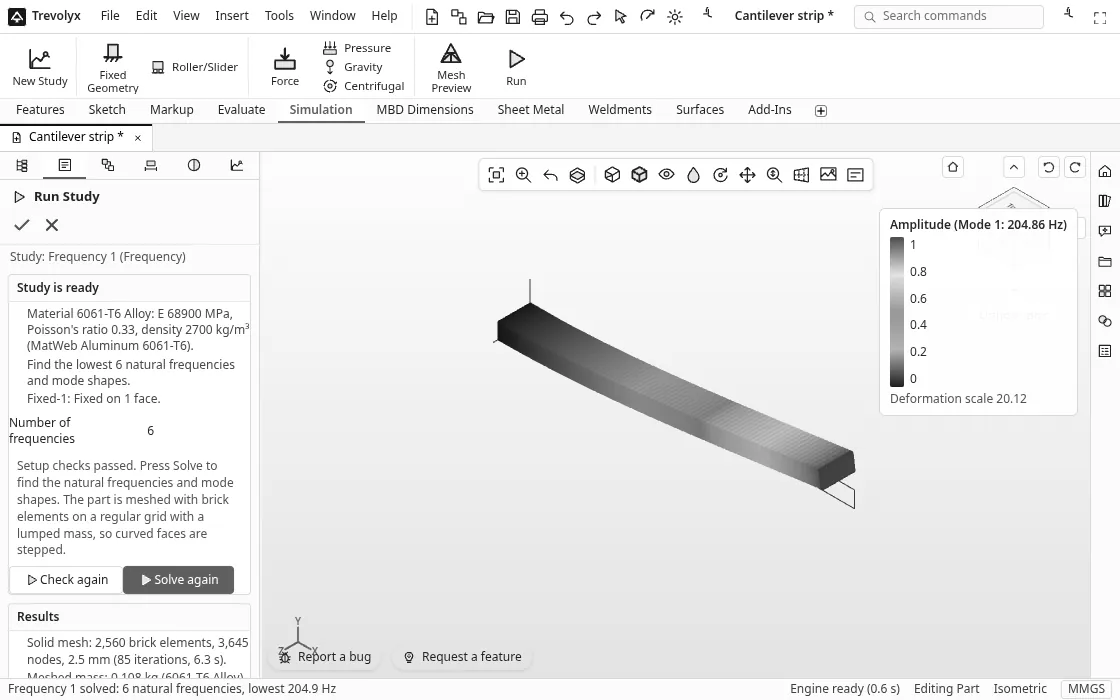
We modelled the strip on the live Trevolyx app on 19 Nov 2026 and solved it as a frequency study. The steps work on any part:
- Make or open the part and set its material (right click the material in the design tree, then Edit Material...).
- Open the Simulation tab and press New Study. It starts a static study and opens the study tree; pick Frequency in the box next to New Study there and press New Study again. You can delete the empty static study.
- Pick Fixed Geometry and click the clamped end face.
- Under Mesh, type an element size. We used 2.5 mm, which puts four elements through the thickness.
- Press Run, set Number of frequencies (we asked for 6) and press Solve.
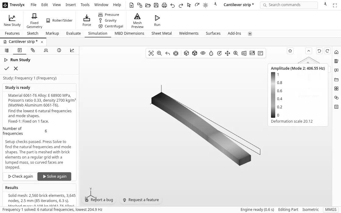
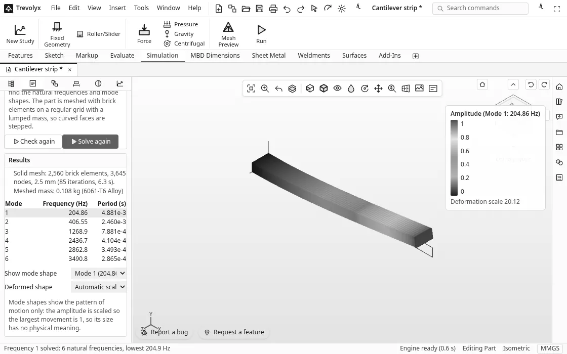
No loads are needed: natural frequencies depend only on shape, material and supports. The solve took 6.3 seconds on a shared server, using 2,560 brick elements, and the meshed mass came out at 0.108 kg, which matches 200 × 20 × 10 mm of aluminium exactly.
Hand calculation vs Trevolyx
| Mode | Shape | Hand calculation | Trevolyx | Difference |
|---|---|---|---|---|
| 1 | 1st bend through the thickness | 204.0 Hz | 204.86 Hz | +0.4% |
| 2 | 1st bend across the width | 408.0 Hz | 406.55 Hz | -0.4% |
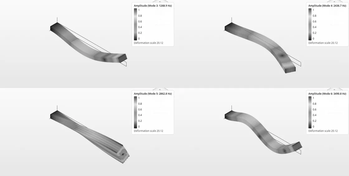
| 3 | 2nd bend through the thickness | 1,278.5 Hz | 1,268.9 Hz | -0.8% |
| 4 | 2nd bend across the width | 2,557.0 Hz | 2,436.7 Hz | -4.7% |
| 5 | 1st twist (torsion) | 2,870 Hz | 2,862.8 Hz | -0.3% |
| 6 | 3rd bend through the thickness | 3,579.8 Hz | 3,490.8 Hz | -2.5% |
The first three modes and the twist all land within 1% of the hand values. Modes 4 and 6 come in a few per cent lower, and that is the formula's fault, not the solver's.
Why the higher modes drift
Euler-Bernoulli theory assumes the beam is long and thin, so it ignores two things: shear deformation and the inertia of each slice rotating as the beam bends. Both make a real beam a little softer and slower than the formula says, and both grow when the wave along the beam gets short compared with the depth.
Our strip is only 10 times longer than it is wide. In mode 4 the beam bends in an S shape across that 20 mm width, so each half wave is short and stubby, and the 3D solid model comes out 4.7% lower. A thicker beam theory (Timoshenko) or a solid FEA model like this one captures that. As a rule of thumb, trust the simple formula for the first mode when the length is at least 10 times the depth in the bending direction, and check higher modes with FEA.
| Element size | Bricks | Solve time | Mode 1 | Mode 2 | Mode 5 (twist) |
|---|---|---|---|---|---|
| 5 mm | 320 | 2.0 s | 205.05 Hz | 407.03 Hz | 2,754.5 Hz |
| 2.5 mm | 2,560 | 6.3 s | 204.86 Hz | 406.55 Hz | 2,862.8 Hz |
| 1.25 mm | 20,480 | 40.1 s | 204.75 Hz | 406.32 Hz | 2,890.3 Hz |
Bending modes barely move with the mesh. The twist needs a finer mesh, because a 5 mm brick puts only two elements across the thickness, too few to follow the warping of the section. Always run one finer mesh before you trust a number.
What to do with the answer
- Compare it with what shakes the part. A motor at 1,500 rpm runs at 25 Hz; a fan with 5 blades at that speed pushes air at 125 Hz. A common target is to keep the first natural frequency at least 2 to 3 times above the highest forcing frequency.
- Shorten it. Frequency goes with 1/L². Cut the length by 20% and the first mode rises by about 56%.
- Thicken it in the bending direction. Frequency grows in proportion to the thickness h, so doubling the thickness doubles the frequency, while doubling the width does nothing for that mode.
- Do not expect steel to fix it. E/ρ is almost the same for steel and aluminium, so the same shape in steel vibrates at nearly the same frequency, just heavier. Change the shape or the supports instead.
Honest limits
- Linear, undamped, small motion. The study finds natural frequencies and mode shapes, not vibration amplitudes, stresses from shaking or fatigue life.
- Mode shape size is not real. The app scales every mode so the largest motion is 1; only the pattern and the frequency carry meaning.
- Parts only, perfect clamps. Studies run on single parts, and Fixed Geometry is perfectly rigid. A real bolted clamp is softer, so measured frequencies usually come in a little lower.
- Brick mesh. Curved faces are stepped by the regular brick grid, so refine the mesh on round parts.
For a static stress check on the same kind of beam, see our free FEA stress analysis guide. The Trevolyx features page lists every Simulation command.
FAQ
What is the formula for the natural frequency of a cantilever beam?
f1 = (1.8751)² / (2π L²) × √(E I / ρA), which simplifies to 0.5596 / L² × √(E I / ρA). For higher modes replace 1.8751 with 4.6941, 7.8548 and so on.
Does adding a mass at the tip change the formula?
Yes. A tip mass lowers the frequency. A quick estimate treats the beam as a spring of stiffness 3EI/L³ carrying the tip mass plus about 0.24 times the beam's own mass. For anything more complicated, model the mass as part of the solid and run a frequency study.
Is there a free modal analysis tool online?
Yes. Trevolyx runs frequency (modal) studies and linear static studies in a desktop browser for free, with no account. The mesh and solve run on your own computer and the model is not uploaded.
Why does my FEA give a lower frequency than the formula?
Usually because the beam is not slender enough for the formula. Shear and rotary inertia lower the real frequency, most of all for higher modes and short, deep beams. A coarse mesh pushes the other way and makes the model too stiff, so run a mesh check.
Can I run a frequency study on a STEP file?
Yes. Open the STEP file in Trevolyx, where it arrives as an exact solid, set the material and follow the same steps. See opening STEP files online.
Sources
- MIT OpenCourseWare 2.002, Euler-Bernoulli Beams: Bending, Buckling, and Vibration (D. M. Parks) (beam vibration equation)
- TU Graz, Cantilever beam normal modes (frequency equation and the βL roots 1.87510, 4.69409, 7.85476)
- MatWeb: Aluminum 6061-T6 material data (modulus and density)
- Torsion constant for a 2:1 rectangle (β = 0.229) from Roark's Formulas for Stress and Strain, torsion of solid rectangular sections
- Every element count, solve time and frequency above was measured on the live Trevolyx Simulation tab on 19 Nov 2026
Written by the TaskNinja team with help from an AI writing tool, then checked against the live app and hand calculations.