How to make a CAD assembly and exploded view in your browser (free, no install)
Build a four part pin fixture in Trevolyx: insert STEP parts, add seven mates, check for clashes, explode it in two steps, get a parts list. Free, no install.
After your first part, the next skill every CAD course expects is the assembly: parts placed together with mates, checked for clashes, then pulled apart into an exploded view with a parts list. This tutorial does all of it on a small real assembly in a browser tab, with nothing to install.
We built it on the live Trevolyx app on 11 Nov 2026, and every button name, count and position below is what the app showed. Download the same three parts and follow along in about twenty minutes.
The assembly: a small pin fixture
A pin fixture uses the two mates you will use most, Coincident and Concentric, and has a repeated part, which makes the parts list interesting. Four components come from three part files.
| Part | Size | Qty in the assembly |
|---|---|---|
| base-plate.step | 100 x 50 x 10 mm plate, two 10.5 mm holes 50 mm apart | 1 |
| clamp-bar.step | 100 x 20 x 8 mm bar, two 10.5 mm holes 50 mm apart | 1 |
| shoulder-pin.step | 16 mm head, 5 mm thick, on a 10 mm shank 18 mm long | 2 |
The shank is 18 mm because the bar and plate stack up to 8 + 10 = 18 mm, so the pin ends flush with the underside. The holes are 10.5 mm for a 10 mm pin, which leaves 0.25 mm of clearance all round. That is the same figure ISO 273 gives as its fine series clearance hole for an M10 bolt, a sensible choice when parts need to line up closely.
We made the parts as STEP files so this post can focus on the assembly. You could also model them in Trevolyx, as in our first CAD part tutorial.
Step 1: start an assembly and insert the parts
- Open Trevolyx in desktop Chrome or Edge and click the Assembly tile on the start screen. A new assembly opens with the Begin Assembly panel on the left.
- Click Browse... and pick base-plate.step. The first component lands at the origin and is fixed. The tree shows it as (f) base-plate<1>.
- Insert clamp-bar.step, then shoulder-pin.step twice. Each new part lands beside the assembly and shows (-) in the tree, meaning it is free to move.
The status bar now reads 4 components and 3 under defined. That second number counts parts that can still move, and mates bring it down.
Step 2: mate the clamp bar to the plate
Click Mate on the Assembly tab. Pick a face, edge or axis on each component. The Mate selections box shows what you picked, for example Face@clamp-bar<1>, and the result previews before you press OK.
- Coincident1: the underside of the clamp bar and the top face of the plate. Use the View Orientation button above the graphics area and choose Bottom to see the underside, click it, switch back to Isometric, then click the top of the plate. Choose Coincident and press OK. The bar drops onto the plate.
- Concentric1: the left hole of the bar and the left hole of the plate. Click inside each hole so the selection reads Hole face (or the hole's circular edge, which gives the same axis). Choose Concentric and press OK.
- Concentric2: the right hole of the bar and the right hole of the plate, the same way.
After these three mates the bar sat at exactly X 0, Y 15, Z 10 mm, square on the plate. The second Concentric stops the bar swinging around the first hole. It works because both parts share the same 50 mm hole spacing; if holes might not line up exactly, a Parallel mate between two side faces is the safer way to stop the rotation.
Step 3: drop in the pins
- Coincident2: the flat underside of the first pin's head and the top face of the clamp bar. From the Bottom view the head underside is a thin ring. Click in the middle of the ring, not on its edge, and check that the selection says Face@shoulder-pin<1>. A click right on a rim picks the circular edge instead, which does not hold the pin upright.
- Concentric3: the round shank of the pin (Cylindrical face) and the left hole of the bar. The pin slides into the hole.
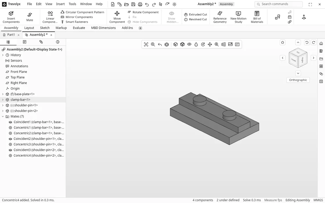
- Repeat for the second pin with Coincident3 and Concentric4 on the right hole.
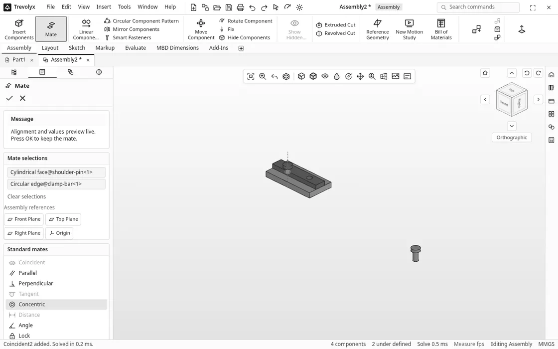
With all seven mates in place the pins sat at X 25 and X 75, Y 25, Z 18 mm, right on the hole centres with the heads on the bar. The status bar still says 2 under defined, and that is correct. A round pin can still spin about its own axis, just as it can in a real fixture. Lock a rotation only when it matters, for example to keep a cross hole facing one way.
Step 4: check for clashes
Before you explode or draw anything, open the Evaluate tab, click Interference Detection and press Calculate. Our run reported No interference for 4 components, with 5 close pairs checked in 7 ms. Clashes would be listed by component pair, which is your cue to go back and fix a part.
Step 5: make the exploded view
- Back on the Assembly tab, click Exploded View.
- Click both pins in the graphics area. The panel says 2 components. Pick the Z direction, type 60 in the distance box and click Add Step. That is Explode Step1.
- Click the clamp bar, keep Z, type 25 and press OK. That is Explode Step2.
Move the outer parts furthest and the inner ones less, so nothing crosses. Here the pins rise 60 mm and the bar 25 mm, leaving a clear gap between every part, and dashed explode lines show where each part goes back.
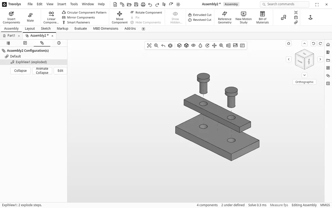
The view is stored as ExplView1 on the ConfigurationManager tab. Exploding does not change the assembly: the mated positions were identical before and after.
Step 6: get a parts list
- On the Assembly tab click Bill of Materials. Trevolyx opens a new drawing of the assembly. Accept the sheet format (ours was A3 at a 2:1 scale).
- Add the standard three views of the assembly from the View Layout tab.
- Open the Annotation tab, click Bill of Materials and click where the table should go.
| Item no. | Part number | Qty. |
|---|---|---|
| 1 | base-plate | 1 |
| 2 | clamp-bar | 1 |
| 3 | shoulder-pin | 2 |
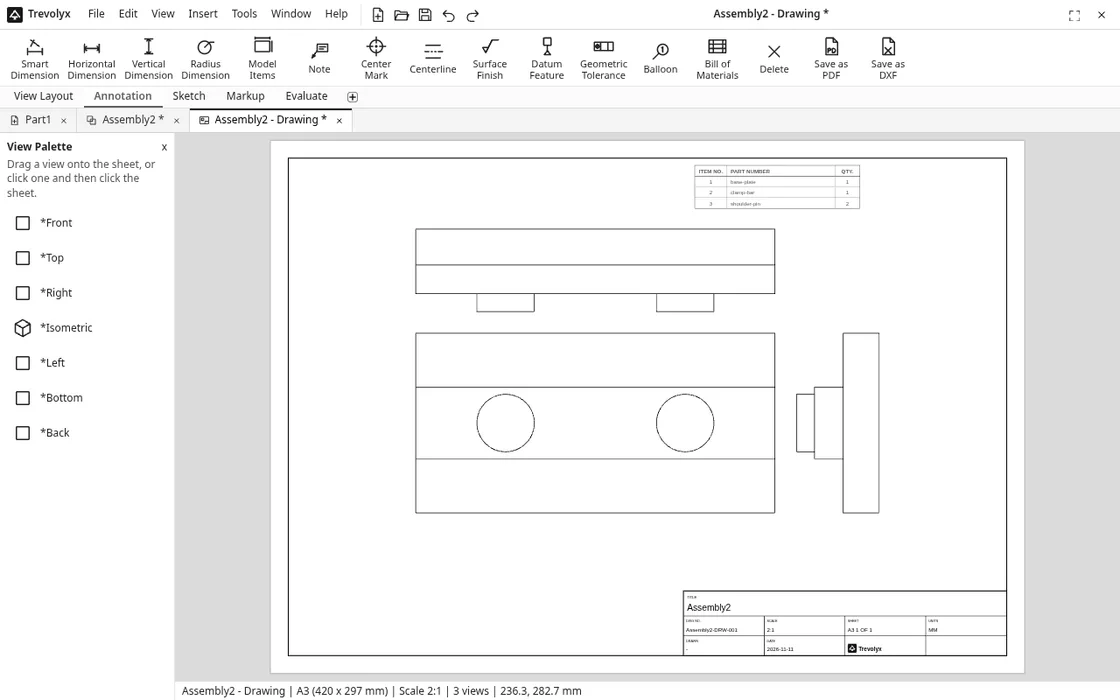
The two pins come from one file, so they share a line with quantity 2. That matches ISO 7573, the standard for parts lists, which lists every constituent with a reference number, quantity and part number. Name part files the way you want them to read on the shop floor, because those names become the part numbers. The Balloon command on the same tab tags parts on a view with their item numbers.
Common mistakes
- Mating to an edge when you meant a face. Read the Mate selections box before pressing OK. A Circular edge gives an axis, not a flat face.
- Fighting the under defined count. Parts that can only spin about their own axis are fine. Chase the count down only for parts that can still slide or tip.
- Holes and pins the same size. A 10 mm pin in a 10 mm hole leaves no clearance. Pick the hole from the standard your shop uses.
Honest limits
Trevolyx is desktop first, so use a laptop rather than a phone. In assemblies, Measure and Mass Properties are not available yet, and neither are Smart Fasteners, motion studies or section views. Drawings show the assembled state, so for instructions we take the exploded picture from the assembly window. Native SolidWorks or Inventor files do not open; export STEP from those programs. Small faces like the pin head may take a couple of clicks to pick.
FAQ
Is Trevolyx really free for assemblies?
Yes. Mates, interference detection, exploded views and the parts list are all in the free browser app, with no account. Files stay on your computer.
Can I use STEP files from a supplier in an assembly?
Yes. Insert Components accepts STEP and IGES files as well as Trevolyx parts. They come in as exact solids and mate like any other part, which is how this tutorial was built.
Why does my assembly still say under defined?
At least one part can still move. Round parts such as pins and shafts often keep one free rotation, which is usually fine. If a part can still slide, add a Coincident or Distance mate.
How do I make the exploded view go back together?
Open the ConfigurationManager tab and click Collapse under ExplView1, or use Animate Collapse to watch the parts move back in order.
Does the parts list update when I add parts?
Yes. It is built from the components in the assembly, so a third pin of the same file would show as quantity 3 on the same line.
Sources
- ISO 273:1979, Fasteners, Clearance holes for bolts and screws (M10: fine 10.5 mm, medium 11 mm, coarse 12 mm)
- ISO 7573:2008, Technical product documentation, Parts lists
- Tutorial parts: base-plate.step, clamp-bar.step, shoulder-pin.step
- Trevolyx live app, all steps, positions and results above run on 11 Nov 2026
- Assemblies and exploded views, 2D engineering drawings, 3D CAD hub
Written by the TaskNinja team with help from an AI writing tool, then checked against the live Trevolyx app and the ISO catalogue entries.