Build assemblies with mates, exploded views and a BOM
Insert parts, add mates, pattern components, check interference, create an exploded view and place a bill of materials with balloons on a drawing. Free in your browser.
Open TrevolyxFree, desktop browser, nothing uploaded.
From parts to a product
Real products are assemblies. A gearbox is housings, shafts, bearings and fasteners; a jig is a base plate, locators and clamps. Assembly modelling lets you position those parts with mates, check that they fit, and document how they go together with an exploded view and a parts list. Trevolyx follows the SolidWorks assembly workflow so the steps will feel familiar.
Step by step
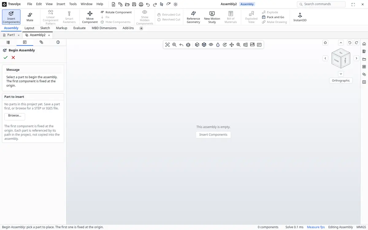
- Click Assembly on the start screen. Use Insert Components to place saved .tnprt parts or STEP files. The first component is fixed at the origin.
Insert Components in a new assembly - Click Mate and pick two faces, edges or axes. Coincident, parallel, perpendicular, concentric, tangent and distance mates position the parts.
- Use Linear Component Pattern for rows of bolts or rollers.
- Run Interference Detection from the Evaluate tab to find parts that overlap.
- Click Exploded View and drag components apart along their axes. The explode steps are stored so you can collapse and explode again.
- Make a drawing of the assembly, add the exploded view, then place a Bill of Materials and Balloons.
Assembly tools in v1
| Tool | Available |
|---|---|
| Insert Components (parts and STEP) | Yes |
| Standard mates | Yes |
| Linear Component Pattern | Yes |
| Interference Detection | Yes |
| Exploded View | Yes |
| Bill of Materials and Balloons on drawings | Yes |
| Section view inside assemblies | Coming in a later build |
| Motion study and simulation | Not yet |
Good habits
Keep each assembly and its parts in one project folder so references stay intact. Name parts clearly, because those names appear in the BOM. Mate to planes and axes where possible rather than to fillet edges, which can change when you edit a part.
Mates explained in plain terms
A mate is a rule between two components. Coincident puts two faces or points together. Parallel and perpendicular set face directions. Concentric lines up two cylinders, like a shaft in a bore. Tangent keeps a cylinder touching a flat face. Distance and angle hold a set gap or tilt. Each mate removes some freedom of movement; when every freedom is removed the component is fully defined.
Start by fixing the first component, usually the base or housing. Then add parts one at a time, mating each to something already placed. Leaving a component with one degree of freedom on purpose, such as a shaft that can spin, lets you drag it and check motion.
Using exploded views and BOMs
An exploded view moves components apart along clear directions so a reader can see how they go together. It is the standard picture in assembly instructions, service manuals and patent drawings. Add steps one at a time, pulling the outer parts away first. The assembled positions are untouched; you can collapse and explode the view at any time.
In a drawing, place the exploded view, add a Bill of Materials table and attach Balloons to each part. The balloon numbers match the item numbers in the BOM automatically, which is what most workshop and vendor documentation needs.
Checking an assembly
Interference Detection lists every pair of components that overlap, with the volume of the clash. Clearance Verification checks that chosen parts keep a minimum gap. Mass Properties on the whole assembly gives total weight and centre of gravity. Use Linear Component Pattern for repeated parts such as bolts along a flange, so changing the count updates every copy.
Typical student and shop projects
Classic machine drawing assemblies make excellent practice: a screw jack, a plummer block, a knuckle joint, a cotter joint, a tailstock or a machine vice. Each has five to fifteen parts, a clear base component and simple mates. For a workshop, a fixture, a conveyor roller or a small gearbox housing teaches the same skills with real value. Model each part, assemble with mates, add an exploded view and finish with a drawing that has a BOM and balloons. That set of files is a strong portfolio piece for interviews.
Building the assembly first
Insert Components brings parts into the assembly, and Mate positions them. Use coincident, parallel and concentric style mates to fix parts the way they fit in real life, and a Linear Component Pattern to repeat fasteners. Interference Detection on the Evaluate tab checks for clashes before you explode anything.
When the assembly behaves correctly, create the Exploded View and move components out along clear directions, usually the axis of each bolt or shaft.
Using the exploded view on drawings
Place the exploded configuration on a drawing sheet, add balloons to each component and insert a bill of materials. Save as PDF for assembly instructions or as DXF for further editing. This is a common way to produce clear build instructions for a workshop or a customer.
Frequently asked questions
Can I check for clashes?
Yes. Interference Detection and Clearance Verification are on the Evaluate tab.
Can I use STEP files from suppliers in an assembly?
Yes. Insert them as components and mate them like native parts.
How many parts can an assembly have?
It depends on your computer. Dozens of parts are comfortable on a typical laptop; very large assemblies will be slower than desktop CAD.
Does the BOM update automatically?
Yes, it is generated from the components in the assembly.