Your first CAD part: draw, extrude and drill a mounting plate in the browser
A beginner CAD tutorial you can finish in 15 minutes: sketch a rectangle, extrude it, cut two holes and read the mass, all free in your browser with Trevolyx.
Most beginner CAD tutorials start with a software install, a student licence form and a 40 minute video. This one does not. You need a laptop with desktop Chrome or Edge, and about fifteen minutes. By the end you will have a real part: an 80 by 40 by 6 mm mounting plate with two holes, with its volume and mass read out by the program.
A flat plate with bolt holes is a classic first exercise, and it teaches the loop you will repeat for years: sketch, constrain, feature, check. We ran every step below on the live Trevolyx app on 9 Nov 2026, so the button names and numbers are what you will see.
What you are going to build
| Item | Value |
|---|---|
| Plate size | 80 mm long, 40 mm wide, 6 mm thick |
| Holes | Two, 8 mm diameter, centred 12 mm and 68 mm from the left edge, 20 mm up |
| Features | Boss-Extrude1 (the plate), Cut-Extrude1 (both holes in one cut) |
| Volume after the cut | 18,597.2 mm³ (a plain 80 x 40 x 6 block is 19,200 mm³) |
| Mass in plain carbon steel | 145.059 g at the 7800 kg/m³ density Trevolyx uses |
Step 1: open Trevolyx and start a part
- Open Trevolyx in desktop Chrome or Edge. There is no account and nothing to install.
- On the start screen click the Part tile ("A single 3D solid"). An empty Part1 opens with the Front, Top and Right planes and the Origin in the feature tree.
- Wait for the status bar to say Engine ready. That is the geometry kernel finishing its load in your tab.
If you have used SolidWorks the layout will look familiar on purpose: menu bar, command tabs (Features, Sketch, Evaluate and so on), a feature tree on the left and the graphics area on the right.
Step 2: sketch the outline on the Front Plane
- Open the Sketch tab and click Sketch. The panel asks for a plane. Pick Front Plane. The view turns to face the plane and the status bar says Editing Sketch1.
- Choose Corner Rectangle. Click once on the origin (where the red axes meet), then click again up and to the right. The rectangle gets horizontal and vertical relations automatically.
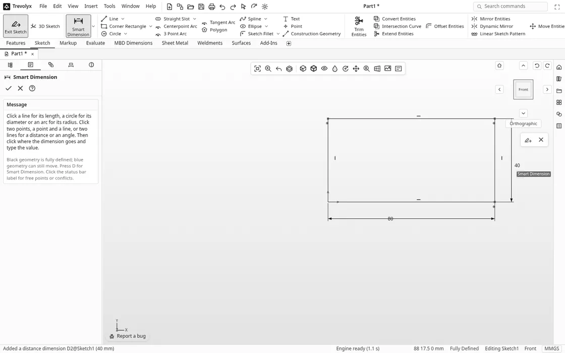
- Choose Smart Dimension. Click the bottom line, then click below it to place the text, type 80 and press Enter. Click the right line, place the text to its right, type 40 and press Enter.
The status bar changes from Under Defined to Fully Defined, and the blue lines turn black. That colour change is the single most useful habit in sketching. Blue means something can still move. Black means the sketch is locked down by dimensions and relations, so the part will not change shape when you edit it later.
Step 3: extrude the plate
- Click Exit Sketch (or the green tick in the corner of the graphics area).
- Open the Features tab and click Extruded Boss/Base. Sketch1 is picked for you.
- Type 6 in the depth box. A preview of the plate appears in the graphics area. Click the green OK tick.
The tree now lists Boss-Extrude1 with Sketch1 nested under it, and Solid Bodies shows one body. Our run reported a volume of exactly 19,200 mm³, which is 80 x 40 x 6, so the kernel agrees with the arithmetic. Comparing a volume with a number you can work out by hand catches many mistakes.
Step 4: sketch the holes and cut them
Holes are just another sketch plus a cut. Start a new sketch on the Front Plane again, so it sits on the same face the plate was drawn from.
- In the Sketch tab click Sketch, pick Front Plane, then choose Circle.
- Click once for the centre of the left hole, then click a short distance away to set the radius. Choose Circle again and do the same for the right hole.
- For a hole you plan to put a real bolt through, use Smart Dimension to set the diameter, and dimension each centre from the edges so the sketch goes black. Our test circles came out at 8 mm diameter with centres 12 mm and 68 mm from the left edge, 20 mm up.
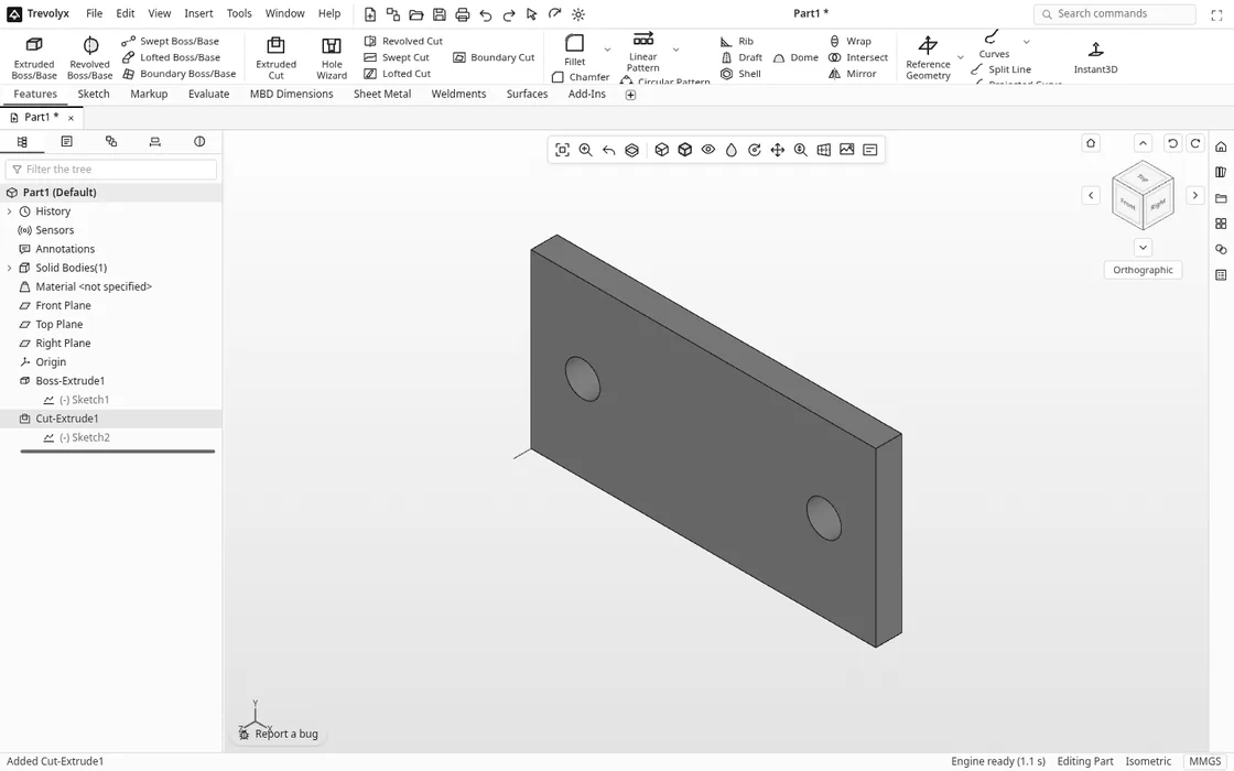
- Exit the sketch, open Features, and click Extruded Cut. In the End Condition list choose Through All, then click OK.
The tree gains Cut-Extrude1. The kernel reported 18,597.2 mm³, against 18,596.8 mm³ from the textbook figure of 19,200 minus two cylinders of 8 mm diameter and 6 mm depth. The 0.4 mm³ gap is the circle being approximated, which is far below anything a drawing would tolerate.
Step 5: check the part with Mass Properties
- Open the Evaluate tab and click Mass Properties.
- In the Material list pick Plain carbon steel. The density field fills in with 7800 kg/m³.
- Read the results panel: mass, volume, surface area, bounding box, centre of mass and the moments of inertia.
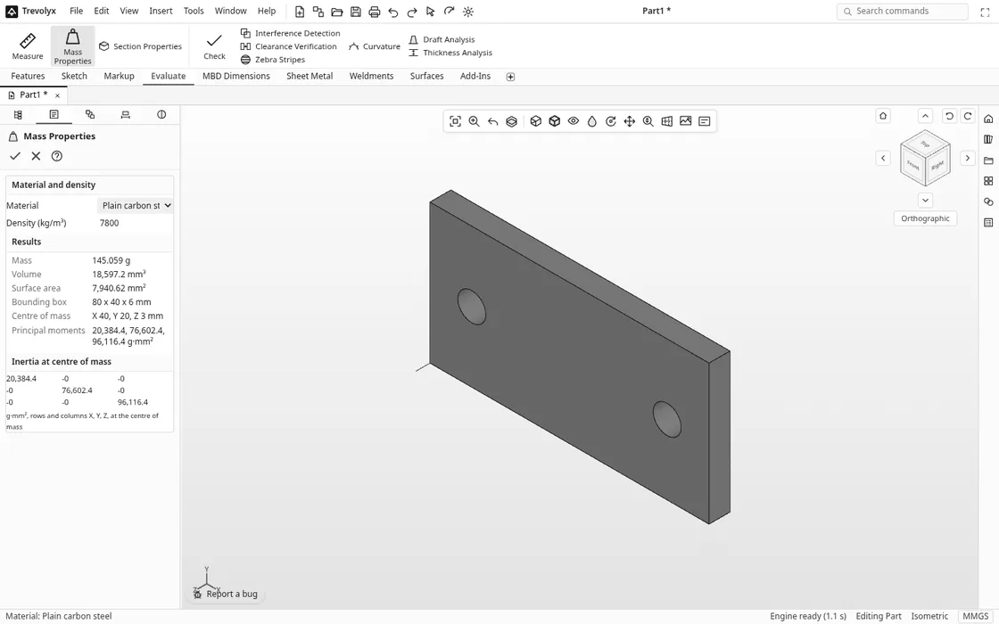
Our plate came out at 145.059 g with a bounding box of 80 x 40 x 6 mm and a centre of mass at X 40, Y 20, Z 3 mm, exactly the middle of the plate. The material list also has aluminium 6061, brass, copper, ABS and PLA.
Common beginner mistakes
- Leaving the sketch under defined. If lines are still blue, add a dimension or a relation. Extrudes work on a loose sketch, but the part can jump when you edit it.
- Holes that cut nothing. A cut only removes material it passes through. If the volume does not drop after the cut, the hole sketch is on a different plane or the end condition is too short. Through All avoids the second problem.
- Using any diameter for a real bolt. An 8 mm hole is fine for practice. For a real bolt, pick the hole from the clearance table in ISO 273, which lists fine, medium and coarse series for each thread size. The medium series is the standard choice for general work.
Where to go next
Add rounded corners with Fillet, a Chamfer on the hole edges, or turn the plate into an L bracket by adding a second sketch and extrude. Once you are comfortable, the free CAD for students page has a seven day practice plan that moves on to revolves, patterns, sheet metal and assemblies. If you are coming from SolidWorks, the free SolidWorks alternative page lists what matches and what does not, and the 3D CAD hub links to everything else.
Save your work with Ctrl+S as a .tnprt file on your own computer, or use File and Export to write STEP or STL if you want to print the plate. Your files stay in the browser tab and are not uploaded.
Honest limits
Trevolyx is desktop first, so use a laptop rather than a phone. It does not open native SolidWorks or Inventor files; export STEP from those programs instead. Simulation, 3D Sketch, Markup and MBD are not in version 1. In our automated run the steps worked as written, but we placed the hole circles by clicking exact coordinates, so treat the exact hole positions as an example and dimension them yourself.
FAQ
Do I need to install anything to follow this tutorial?
No. Trevolyx runs in desktop Chrome or Edge. Open the site, click Part and start sketching. There is no account and no licence.
How long does a first part take?
About fifteen minutes for the plate above, including reading the Mass Properties panel.
What does Fully Defined mean?
Every point and line in the sketch is fixed by dimensions or relations, so nothing can move unintentionally. The lines turn from blue to black. It is good practice for any sketch that will drive a feature.
Can I make the holes a standard bolt size?
Yes. Set the circle diameter to the clearance size for your bolt from ISO 273, or use Hole Wizard in the Features tab, which has counterbore, countersink and tapped holes.
Will this teach me SolidWorks?
The ribbon, the feature tree and the command names follow SolidWorks, so the sketch, constrain, extrude, cut loop carries over. Trevolyx is a different program and does not open native SolidWorks files.
Sources
- ISO 273:1979, Fasteners, Clearance holes for bolts and screws (fine, medium and coarse series, general purpose applications)
- Trevolyx live app, all steps, volumes and masses above run on 9 Nov 2026
- Free CAD for students, free SolidWorks alternative, 3D CAD hub
Written by the TaskNinja team with help from an AI writing tool, then checked against the live Trevolyx app and the ISO catalogue entry.