How to make a 2D engineering drawing from a 3D model (free, in your browser)
Turn a 3D part into a dimensioned 2D drawing with front, top, side and section views, then save a PDF and a DXF. A worked example, free in your browser.
To make a 2D engineering drawing from a 3D model, open the part in a CAD program, start a drawing sheet, place the standard views, add dimensions and a section, then save the sheet as a PDF for people and a DXF for machines. You can do all of that free in a browser tab with Trevolyx, our 3D CAD app. There is nothing to install and the file stays on your computer.
This guide walks through one real part from start to finish. We ran every step on 18 Nov 2026 and the sizes, view names and file details below are what the app reported. Where the app does not do something yet, we say so.
The part we are drawing
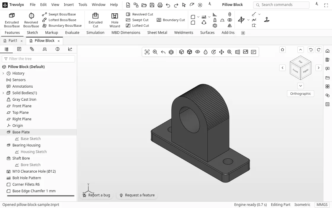
We used the pillow block that Trevolyx ships as a sample, because it has the things a drawing has to explain: an overall size, a bore, two bolt holes, fillets and a chamfer. You can open the same file with one click: open the pillow block sample. It opens with its full feature tree, so you can change it later and watch the drawing follow.
| Feature | Size |
|---|---|
| Overall size (length x depth x height) | 128 x 44 x 88 mm |
| Base plate thickness | 12 mm |
| Shaft bore | Ø34 mm, centre 58 mm above the base |
| Bolt holes | 2 x Ø12 mm (M10 clearance), 92 mm apart |
| Plate corners | R6 fillets |
| Base edge | 1 mm chamfer |
Step 1: start a drawing from the part
With the part open, choose File > Make Drawing from Part. A Sheet Format/Size box asks for the paper. You get A4 to A0 and the ANSI sizes A to E. We picked A3 (420 x 297 mm), the usual size for a small machined part. A new drawing tab opens next to the part, with a border and a title block already filled in with the part name, a drawing number, the scale, the units and the date.
Step 2: place the three standard views
Press Standard 3 View. Trevolyx places the front, top and right views, lined up with each other, and picks the largest standard scale that fits. For our part on A3 that was 1:1, so 1 mm on paper is 1 mm on the part. The status bar confirmed it: A3, Scale 1:1, 3 views.
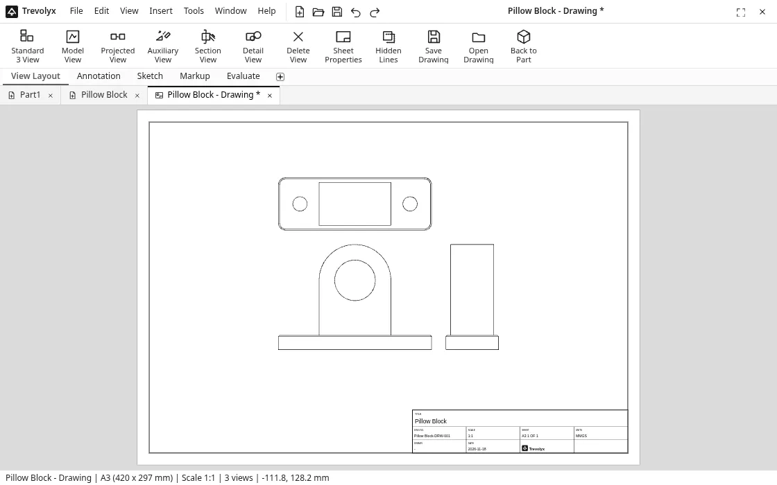
Look at where the top view landed: above the front view. That is third angle projection, used in the USA and many companies that work with American customers. India's drawing standards and most of Europe use first angle, where the top view goes below the front view and the right side view goes on the left (ISO 5456-2 describes both). Trevolyx lays views out in third angle today and has no first angle option yet. If your college or customer asks for first angle, this matters, so read the section on projection below before you send anything.
Step 3: insert dimensions with Model Items
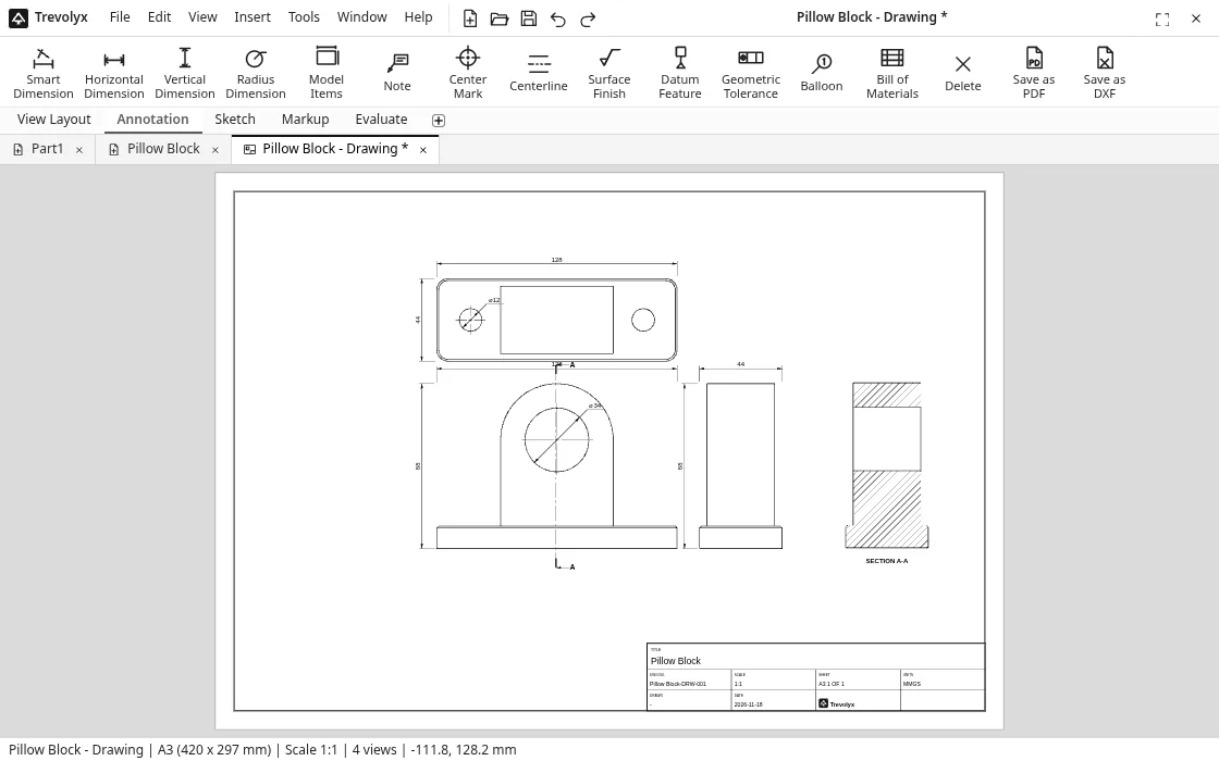
Open the Annotation tab and press Model Items. It adds the overall sizes of every view, the hole and bore diameters, and centre marks. On our sheet it placed 10 annotations: 128 and 88 on the front view with Ø34 on the bore, 128 and 44 on the top view with Ø12 on a bolt hole, and 44 and 88 on the right view. Each diameter is placed once, on the first view where it shows as a circle, which is what you want on a clean drawing.
Model Items does not dimension positions. The bore height (58 mm) and the bolt hole spacing (92 mm) still need adding by hand with Smart Dimension, Horizontal Dimension or Vertical Dimension. Treat Model Items as a fast first pass, not a finished drawing.
Step 4: add a section through the bore
The inside of the bore is invisible in the outside views, so we cut it open. On the View Layout tab choose Section View, click across the middle of the front view to set a vertical cutting line, then click to the right to place the result. Trevolyx labels the cut A-A on the front view, draws the new view with hatching on the cut material, and titles it SECTION A-A. You can switch the cutting line to horizontal in the bar that appears while you place it.
If you need a small feature bigger, Detail View draws a circle on a view and places an enlarged copy. Projected View adds more directions from any view you select, and Hidden Lines switches between hidden lines removed and shown dashed.
Step 5: fill in the title block
Open Sheet Properties on the View Layout tab to set the title, drawing number and your name under Drawn by. You can change the sheet size and scale there too. Add notes with the Note tool for material, finish and a general tolerance line.
Step 6: save as PDF and DXF
Both buttons are on the Annotation tab. Save as PDF writes a vector PDF at true sheet size, and Save as DXF writes a 2D CAD file in millimetres. We checked both files outside the app:
| Check | DXF | |
|---|---|---|
| File size | 13.1 KB | 31.5 KB |
| Sheet | A3, 1190.55 x 841.89 pt (420 x 297 mm) | Border 400 x 277 mm inside 10 mm margins |
| Scale | Vector, print at 100% | 1:1, units set to millimetres |
| Format | One page, PDF from Trevolyx | DXF R12 (AC1009), an old version almost every 2D program reads |
| Content | Lines, hatching, dimensions, title block | 439 lines, 26 text items and 18 filled arrowheads; Ø written as the standard %%c code |
| Layers | Not used | VISIBLE, HIDDEN, THIN, TEXT |
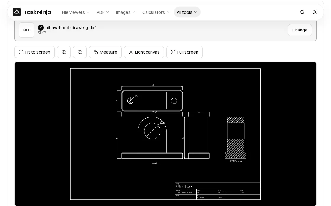
We measured the front view in the DXF: it is exactly 128.0 mm wide, the same as the part, so a vendor can measure straight off it. Dimensions arrive as plain lines and text rather than live dimension objects, which keeps the file readable by older programs. To check a DXF before you send it, open it in the free DXF viewer.
First angle or third angle: what to do today
A drawing read in the wrong projection is a part made wrong, because the top and bottom (or left and right) swap. Every drawing should carry the projection symbol or a note. Since Trevolyx lays out third angle, add a note such as THIRD ANGLE PROJECTION near the title block so nobody guesses.
If you must hand in a first angle sheet, for example an engineering drawing assignment, Trevolyx is not the right tool for that sheet yet. You can still model the part, take its sizes from the drawing, and use the DXF as a base in a 2D program. We will update this guide when a first angle option ships.
A short checklist before you send it
- Every feature has a size and a position. Model Items gives sizes; add positions such as hole spacing yourself.
- Nothing is dimensioned twice. If the same size shows on two views, delete one.
- Title block filled in: title, number, scale, material, your name and a revision.
- Projection stated, with a note or the symbol.
- Print the PDF at 100% on the right paper and measure one known dimension with a ruler.
What it cannot do yet
- First angle layout. Views are placed in third angle only, as covered above.
- Automatic position dimensions. Model Items adds sizes and diameters, not locations.
- Live DXF dimensions. Dimensions are exported as lines and text.
- Dimensions that follow the model. Views redraw when the part changes, but placed dimensions keep their values. Re-insert them after an edit.
- Phones. Trevolyx is built for a laptop or desktop with a mouse. The DXF viewer works on a phone.
FAQ
Can I make a 2D drawing from a 3D model for free?
Yes. In Trevolyx open or model the part, choose File > Make Drawing from Part, press Standard 3 View, then save as PDF or DXF. It is free and needs no account. Desktop Chrome and Edge are fully tested; Firefox and Safari also load it.
Can I make a drawing from a STEP file?
Yes. Open the .step or .stp file in Trevolyx and use Make Drawing from Part in the same way. The views come from the shape in the file, so they are correct even though an imported part has no editable feature history.
Do the drawing views update when I change the part?
The views do. We changed the bore from Ø34 to Ø30 in the part, went back to the drawing tab and the front view redrew with the smaller circle. Dimensions you already placed keep their old numbers, though, so delete them and run Model Items again after any change.
Is the DXF to scale?
Yes. The DXF is written in millimetres at 1:1 sheet size. Our 128 mm front view measured 128.0 mm in the file.
Which projection does Trevolyx use?
Third angle: the top view goes above the front view and the right view to its right. There is no first angle option yet.
Sources
- ISO 5456-2:1996, Technical drawings, Projection methods, Part 2: Orthographic representations (first angle and third angle view placement and their symbols; confirmed current in 2025)
- Library of Congress: DXF (Drawing Interchange Format) family, ASCII variant (what a DXF file holds and why it is used for exchange)
- ISO 216: A series paper sizes (A3 is 420 x 297 mm)
- Every view, dimension and file detail above was produced in Trevolyx on 18 Nov 2026 and checked with pdfinfo and ezdxf
Written by the TaskNinja team with help from an AI writing tool, then checked step by step in Trevolyx.