Sheet metal flat pattern length: K-factor, bend allowance and bend deduction, worked on a real bracket
Work out a sheet metal flat pattern by hand with the K-factor, bend allowance and bend deduction, then check it in free browser CAD and export the DXF.
A laser shop cuts your bracket from a flat blank and a press brake folds it. If the blank is half a millimetre too long, a box with four bends can be two millimetres out. The blank size is the flat pattern length, and it hangs on one small ratio called the K-factor.
This guide works one L bracket through: the formulas by hand, the same part in Trevolyx (our free browser CAD), and the DXF for the shop. Every flat length below was reported by the live app on 10 Nov 2026, and each matches the hand calculation.
The bracket
| Item | Value |
|---|---|
| Material thickness T | 2 mm |
| Inside bend radius R | 2 mm |
| Bend angle A | 90° |
| K-factor K | 0.44 |
| Base leg (outside) | 50 mm |
| Flange leg (outside) | 30 mm |
| Width | 100 mm |
Three terms you need
When sheet bends, the inside face is squashed and the outside face stretches. Somewhere between them is a layer that keeps its length, the neutral axis. The K-factor says where it sits: K = t / T, where t is the distance from the inside face to the neutral axis. K = 0.5 means the middle of the sheet, smaller values mean closer to the inside face.
- Bend allowance (BA) is the length of the neutral axis through the bend. SOLIDWORKS Help gives it as BA = π x (R + K x T) x A / 180, with A in degrees.
- Outside setback (OSSB) is how far the bend pulls back from the virtual sharp: OSSB = (R + T) x tan(A / 2). At 90° that is simply R + T.
- Bend deduction (BD) is what you subtract from the two outside legs: BD = 2 x OSSB - BA.
So the flat length is the outside legs minus one bend deduction per bend.
Working it by hand
- BA = π x (2 + 0.44 x 2) x 90 / 180 = 1.5708 x 2.88 = 4.524 mm.
- OSSB = (2 + 2) x tan 45° = 4 mm.
- BD = 2 x 4 - 4.524 = 3.476 mm.
- Flat length = 50 + 30 - 3.476 = 76.524 mm. Check it the other way: straight base 50 - 4 = 46, straight flange 30 - 4 = 26, and 46 + 4.524 + 26 = 76.524.
The bend line a fabricator marks on the blank sits in the middle of the bend zone, at 46 + 4.524 / 2 = 48.262 mm from the base edge.
The same bracket in Trevolyx
- Open Trevolyx in desktop Chrome or Edge and start a Part. Sketch a 100 by 50 mm rectangle on the Front Plane.
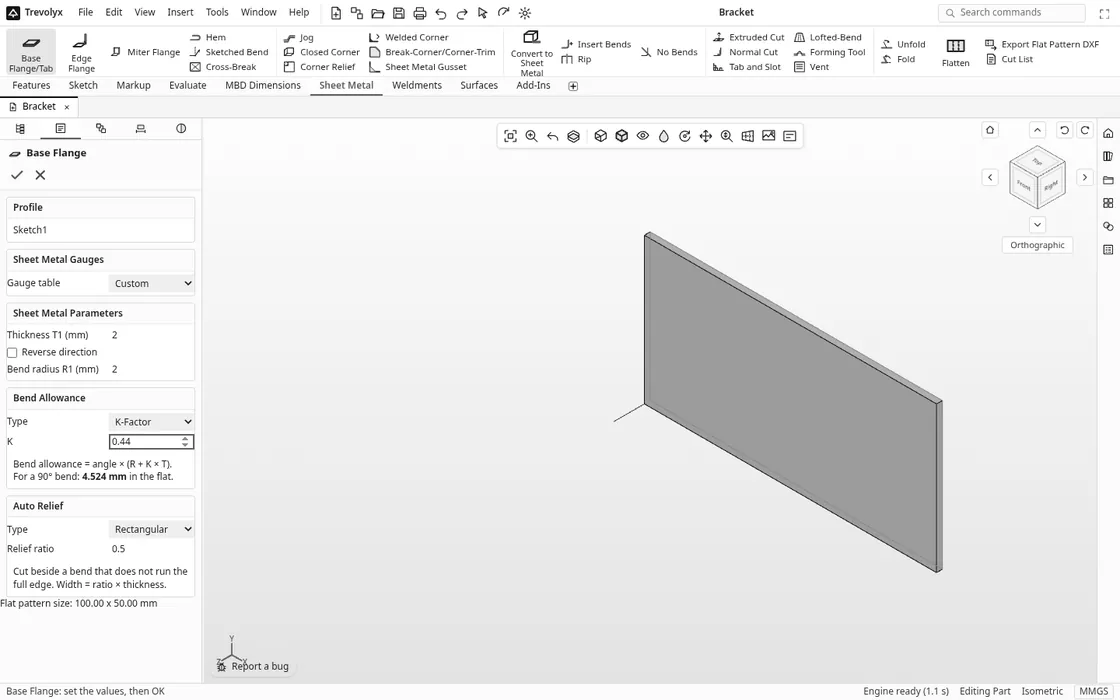
- Open the Sheet Metal tab and click Base Flange/Tab. Leave Gauge table on Custom, set Thickness T1 to 2 and Bend radius R1 to 2. In Bend Allowance, keep the type on K-Factor and type 0.44. The panel works out the allowance for a 90° bend as you type: 4.524 mm, the same as step 1 above.
- Click OK. The tree gains a Sheet-Metal folder with a cut list, Base-Flange1 and Flat-Pattern1.
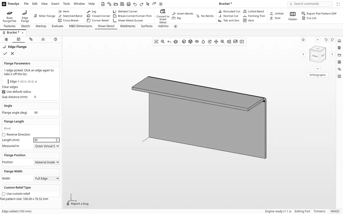
- Click Edge Flange, then click the top edge of the plate. Set Length to 30, leave Measured to on Outer Virtual Sharp and Position on Material Inside. The foot of the panel reads Flat pattern size: 100.00 x 76.52 mm before you even press OK.
How much does the K-factor matter?
We rebuilt the same bracket with three K-factors. Only the bend allowance changes, so the difference per bend is small, but it adds up on a part with four or six bends.
| K-factor | Bend allowance | Bend deduction | Flat length |
|---|---|---|---|
| 0.33 | 4.178 mm | 3.822 mm | 76.178 mm |
| 0.44 | 4.524 mm | 3.476 mm | 76.524 mm |
| 0.50 | 4.712 mm | 3.288 mm | 76.712 mm |
Going from 0.33 to 0.5 moves this one bend by 0.53 mm. Trevolyx starts new parts at K = 0.5, and a SOLIDWORKS blog post on bend allowance options suggests 0.5 when you have no shop data. The best number is still the one your fabricator measures on their own brake, die and material.
The trap: what the flange length is measured to
A flat pattern is more often wrong because the flange length was typed against a different reference than the drawing uses. We kept K at 0.44 and the length at 30 mm, and changed one setting at a time.
| Setting | What 30 mm means | Flat length |
|---|---|---|
| Measured to: Outer Virtual Sharp | 30 to the outside corner | 76.52 mm |
| Measured to: Inner Virtual Sharp | 30 to the inside corner | 78.52 mm |
| Measured to: Tangent Bend | 30 of straight flange after the bend | 80.52 mm |
| Position: Material Outside | Flange sits outside the 50 mm edge | 78.52 mm |
| Position: Bend Outside | Whole bend sits outside the 50 mm edge | 80.52 mm |
That is up to 4 mm from one drop-down. Each row is right for what it describes, so match the setting to your drawing. Most shop drawings give outside dimensions: Outer Virtual Sharp with Material Inside.
Flatten, then export the DXF
- Click Flatten in the Sheet Metal tab to see the blank with its bend line. Click it again to fold the part back.
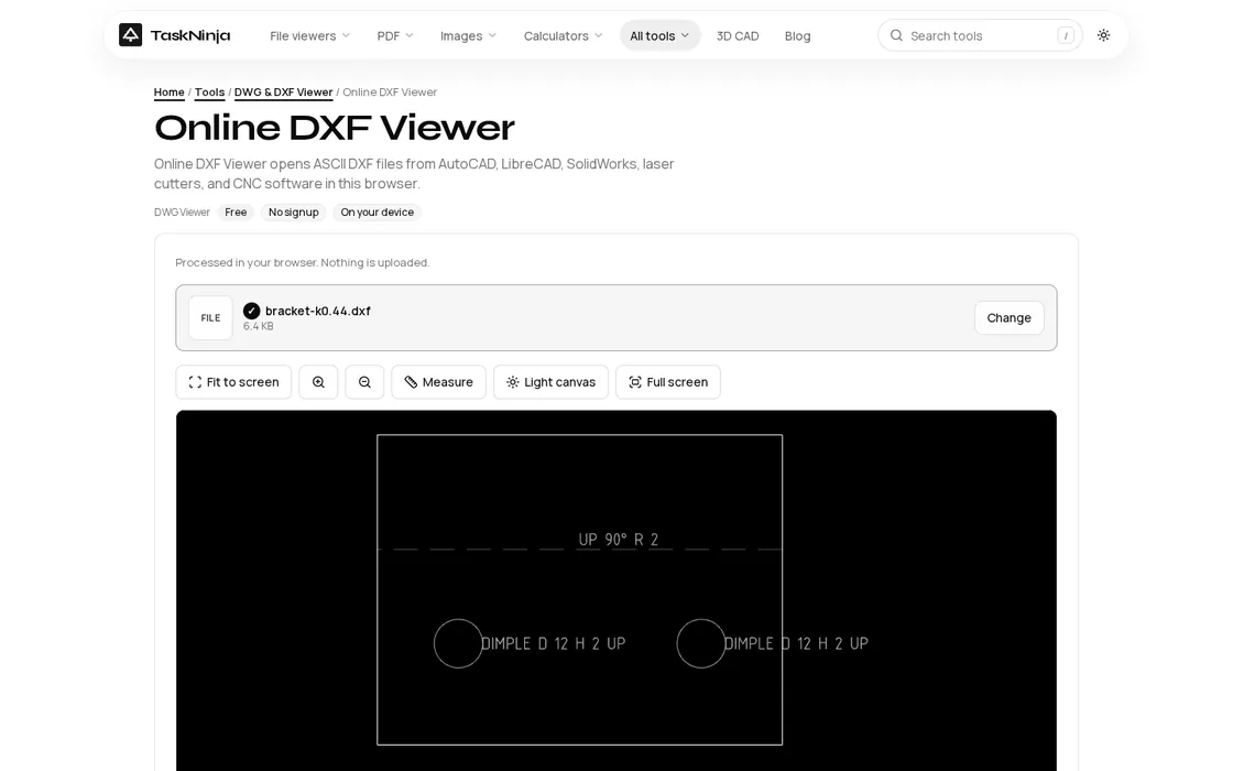
- Click Export Flat Pattern DXF. The file is 1:1 in millimetres with layers for the OUTLINE, the dashed BEND lines, BEND_NOTES such as "UP 90° R 2", and a NOTES block with the cut list: thickness, radius, K-factor, bounding box, blank area and cutting length.
- Open the DXF in the TaskNinja DXF viewer to check it before you send it. Ours showed the 100 x 76.52 outline with the bend line at 48.26 mm, the same as the hand calculation.
We also added two dimples with Forming Tool (Dimple, Louver or Lance). They arrive on their own FORM layer with a note such as "DIMPLE D 12 H 2 UP", and the outline did not change.
Finding your own K-factor from one test bend
- Cut a strip of the real material to a known length L, say 100 mm, and measure the thickness T.
- Bend it to 90° on the same punch and die you will use for the job.
- Measure both outside legs X and Y and the inside radius R.
- BD = X + Y - L. For a 90° bend, BA = 2 x (R + T) - BD.
- K = (BA / 1.5708 - R) / T.
Example numbers: a 100 mm strip of 2 mm sheet with a 2 mm inside radius that measures 51.75 mm on each leg gives BD = 3.5, BA = 8 - 3.5 = 4.5 and K = (4.5 / 1.5708 - 2) / 2 = 0.43. If your shop gives a bend allowance or bend deduction value instead, the Bend Allowance Type list takes those directly.
Honest limits
Trevolyx is desktop first (Chrome or Edge on a laptop). It does not open native SOLIDWORKS or Inventor files, and an imported STEP solid has no sheet metal history, so rebuild it with sheet metal features to flatten it. Excel bend tables are not supported yet. Your files stay in your browser tab.
FAQ
What is a good K-factor for mild steel?
It depends on the radius, die and material. 0.5 is the usual CAD starting point; one test bend gives your shop's real number.
What is the difference between bend allowance and bend deduction?
Bend allowance is the length added for the bend between the two straight parts. Bend deduction is the amount taken off the sum of the outside legs. They describe the same blank from two directions: BD = 2 x OSSB - BA.
Why is my flat pattern 2 mm longer than I expected?
Check what the flange length is measured to. In our test, the same 30 mm typed against the inner virtual sharp instead of the outer one made the blank exactly 2 mm longer.
Can I get the flat pattern DXF free?
Yes. Export Flat Pattern DXF in Trevolyx is free, with no account and no watermark. See the sheet metal flat pattern to DXF page for the full feature list.
Sources
- SOLIDWORKS Help: K-Factor (definition K = t / T and BA = π(R + KT)A / 180)
- SOLIDWORKS blog: Understanding bend allowance options in SOLIDWORKS (K-factor, bend allowance and bend deduction, and the 0.5 starting point)
- Trevolyx live app: every flat length, volume and DXF in this guide was produced on 10 Nov 2026
- Sheet metal flat pattern to DXF, DXF viewer, 3D CAD hub
Written by the TaskNinja team with help from an AI writing tool, then checked against the live Trevolyx app, the hand formulas and the SOLIDWORKS documentation.