Design sheet metal and export the flat pattern to DXF, free
Build sheet metal parts with base flange, edge flange, miter flange and hem, then flatten and export the flat pattern with bend lines as DXF for laser or punch cutting.
Open TrevolyxFree, desktop browser, nothing uploaded.
Why the flat pattern matters
A sheet metal enclosure, bracket or panel starts life as a flat blank. The fabricator cuts the blank on a laser, plasma or turret punch, then bends it on a press brake. The cutting machine needs a 2D DXF of the developed blank, with bend lines marked, and the developed length has to account for the material stretching around each bend. Get the bend allowance wrong and the box does not close.
Trevolyx calculates that flat pattern for you from the folded 3D model, using a K-factor, and saves it as a DXF that any CAM software or job shop can read.
Step by step: bracket to DXF
- Start a new Part. Sketch the profile or the outline of the base on the Front or Top plane.
- Open the Sheet Metal tab and click Base Flange/Tab. Set the thickness, bend radius and K-factor. A K-factor around 0.4 to 0.45 suits mild steel bent in air on a press brake; ask your fabricator for theirs.
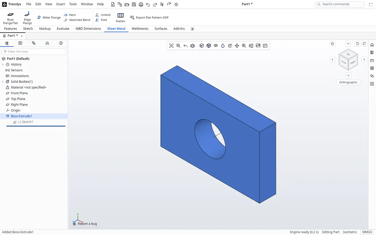
Sheet Metal commands: Base Flange, Edge Flange, Miter Flange, Hem, Flatten - Add Edge Flanges on the edges that need to bend up, Miter Flanges for continuous flanges around corners, and Hems for safe folded edges. Sketched Bend adds a bend along a sketched line.
- Click Flatten to see the developed blank. Click it again to fold the part back.
- Click Export Flat Pattern DXF. The DXF contains the outline and the bend lines. Send it to the laser shop with the material and thickness.
Bend allowance in one paragraph
The neutral axis is the layer inside the sheet that neither stretches nor compresses. Its position is the K-factor times the thickness, measured from the inside face. Bend allowance is the arc length of that neutral axis: BA = angle in radians x (inside radius + K x thickness). Trevolyx uses this to unfold each bend. If your shop gives you a bend deduction table instead, compare a test part with their numbers and adjust the K-factor until the flat length matches.
Sheet metal features in Trevolyx v1
| Feature | Available |
|---|---|
| Base Flange/Tab | Yes |
| Edge Flange | Yes |
| Miter Flange | Yes |
| Hem | Yes |
| Sketched Bend | Yes |
| Unfold and Fold | Yes |
| Flatten view | Yes |
| Export flat pattern DXF with bend lines | Yes |
| Forming tools (louvres, lances) | Not yet |
| Bend tables from Excel | Not yet, use K-factor |
Checking the DXF
Before you send a file to a vendor, open it in the TaskNinja DXF viewer to check the outline is closed and the scale is in millimetres. Many laser shops in India quote from a DXF within the hour, so a clean file saves a round trip.
Understanding the K-factor
When sheet bends, the inside compresses and the outside stretches. Somewhere in between is the neutral axis, a layer that keeps its original length. The K-factor is the position of that layer as a fraction of thickness, measured from the inside face. A K-factor of 0.5 puts it in the middle; real bends in mild steel on a press brake usually land between 0.3 and 0.45.
The flat pattern length depends on it directly, so a wrong K-factor gives parts that come off the brake too long or too short. The best value is the one your fabricator measures on their own tooling. Ask them, set it once in the sheet metal parameters, and every flange in the part uses it. If you have no data, 0.44 is a common starting point for mild steel with an inside radius close to the thickness.
Designing parts that are easy to make
Keep the inside bend radius at least equal to the sheet thickness for steel. Keep holes and slots at least two to three thicknesses away from a bend line so they do not stretch into ovals. Add relief where a flange ends partway along an edge, so the corner can tear cleanly rather than crack. Use the same bend radius throughout a part where you can, because every change of radius can mean a tooling change at the brake.
Flatten the part often while you design. It is the fastest way to catch a flange that overlaps another in the flat, which cannot be cut from a single blank.
Sending the DXF to the laser or punch
The exported DXF contains the outer profile, all cut-outs and the bend lines on a separate layer, at true 1:1 scale in millimetres. Most nesting software reads it directly. Tell the shop the material, thickness, quantity and bend directions, or send the 2D drawing alongside it. Keep the .tnprt file too, so when a dimension changes you can update the model and export a fresh flat pattern in seconds.
Frequently asked questions
Is the flat pattern DXF free to export?
Yes. There is no watermark and no limit.
Which K-factor should I use?
Around 0.33 for tight bends in soft material up to about 0.5 for large radii. Many shops use 0.44 for mild steel. Ask your fabricator.
Are bend lines included?
Yes, the DXF includes the bend lines along with the outline.
Can I import an existing sheet metal STEP and flatten it?
Imported STEP solids come in without sheet metal history, so rebuild the part with sheet metal features to flatten it.